
3D Printing - FDM - Design Guidelines

Expertise
Although a versatile process, FDM has design limitations that must be considered in the design
At first glance, fused deposition modeling printing (FDM) seems quite simple. Indeed, almost all geometries can be manufactured by FDM. However, it is possible to optimize the design of a part in order to have a good finish, to avoid "post-processing" and to keep a desired geometry. It is also important to orient the part on the print bed based on several factors including load cases and the need for support. This blog post lists the limiting characteristics of sizing and shape as well as the main problems encountered when printing by FDM.
Working principle
G-Code: Basic Commands
G28: Homing
G90/G91: Set Position
G1: Linear Mov.
M104/M109: Extrusion Heat
M140/M190: Bed Heat
M106: Fan Speed
The part to be produced is divided into a succession of thin layers which will form the part. The slicer software adjusts the layers according to the options and configurations chosen (supports, Brim/Raft, dimensional adjustments, etc.). The slicer then translates everything into G code which will be transmitted to the 3D printer. The G code includes, among other things, the trajectories, extrusion speed and temperature, fan speed and heating plate temperature.
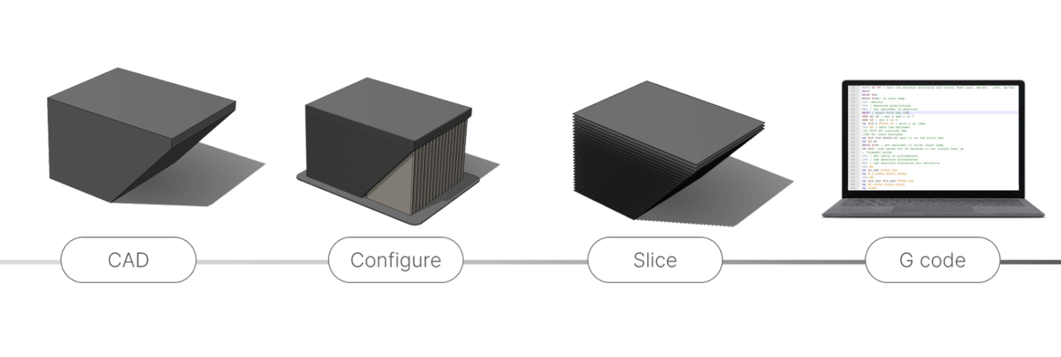
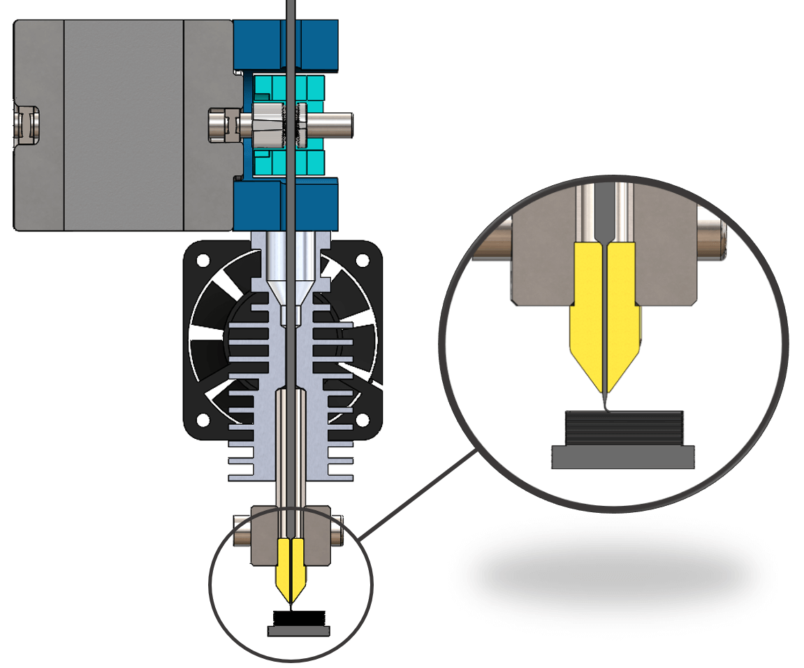 The printer, controlled by a G code, pushes the filament through the nozzle (this nozzle is defined by its internal hole diameter; this diameter is typically 0.4mm). With compression and heat, the plastic is extruded and deposited on top of the previous layers to form the desired part.
Sizing and Shape Characteristics
Layer thickness
The thickness of the layers is in an interval between 25% and 75% of the internal diameter of the nozzle. This means that for a 0.4mm nozzle, the layers have a thickness established between 0.1mm and 0.3mm. In addition, the thickness value should ideally correspond to a physical value linked to the printer configuration. Indeed, the Z axis is powered by a stepper motor coupled to a lead screw. The motor typically found in such an assembly is a NEMA 17 with 200 steps per revolution and the screw is typically a TR8x8 screw: this mechanism therefore creates a translation of 0.04mm per step. We also find motors with 400 steps per revolution equivalent to a translation of 0.02mm per step. It is good to know this specification and to set the layer thickness to a multiple of the translation per step.
For a 0.4mm nozzle, a fine layer height would be 0.12mm, while for a balance between time and quality, a height of 0.2mm would be a reasonable choice
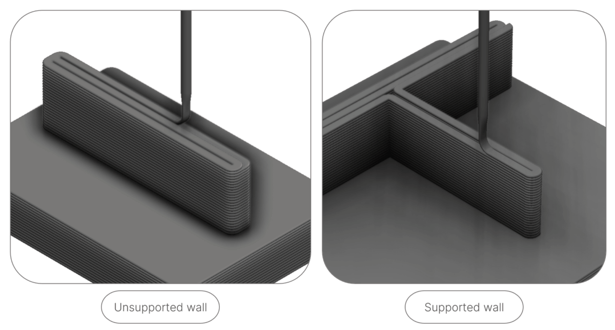
Wall
The rule of thumb tells us that the width of an unsupported wall must be at least three times the nozzle diameter. For a supported wall, we count at least double the nozzle diameter.
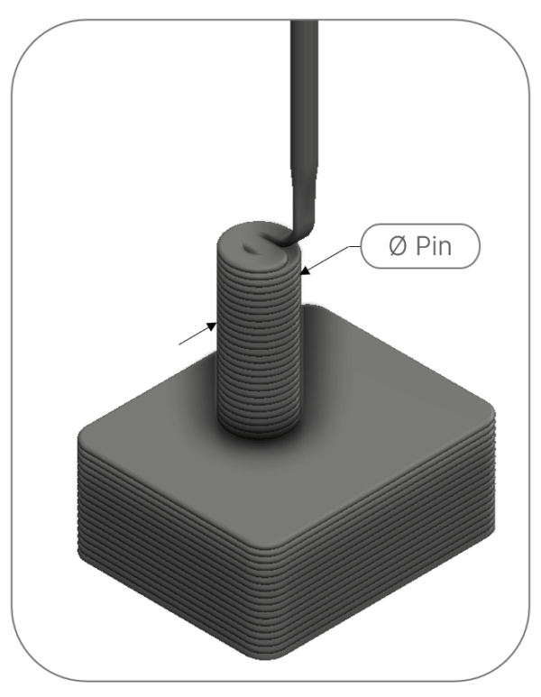
Pin
The minimum diameter size of a pin is 4 times the internal diameter of the nozzle. If the design is suitable, it is recommended to insert an off-the-shelf dowel pin rather than printing it. The structure of the printed stud is very fragile.
Hole
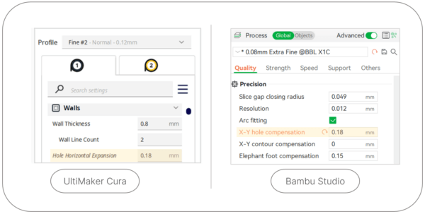
Printed holes are generally undersized. To compensate for undersizing, there are 3 strategies:
- Oversize the hole in CAD: for example, we could size a hole at 8.25mm to aim for a dimension of 8.0mm.
- Configure the number of walls (ex.: 5) in the slicer considering a secondary drilling operation to obtain the desired dimension.
- Configure the slicer by activating an X-Y dimension compensation function.
Overhanged wall
We often hear the 45° rule on overhanging walls, but this rule is as limiting as it is too simplistic. Indeed, the maximum overhang angle (MOA) depends on several factors:
- The printing material
- Nozzle temperature
- The internal diameter of the nozzle
- The thickness of the layers
- The percentage of superposition of the trajectories
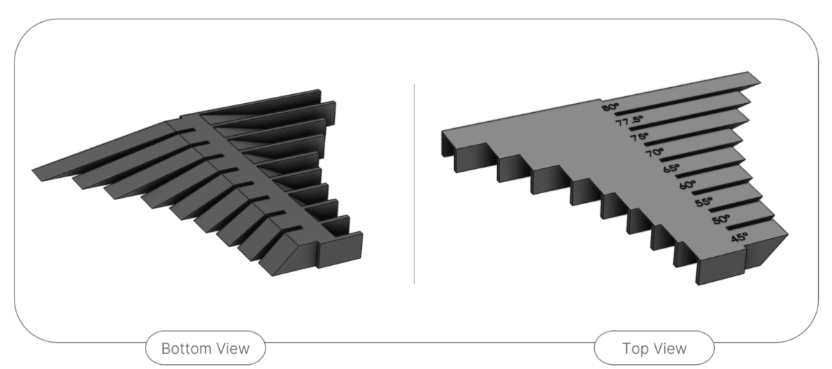
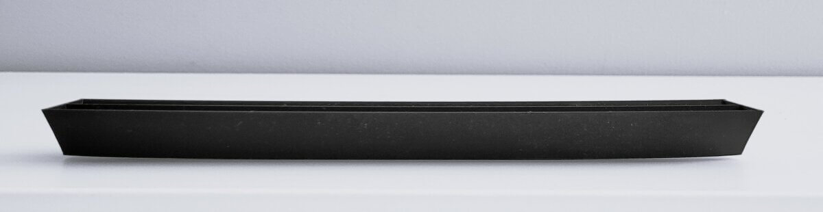
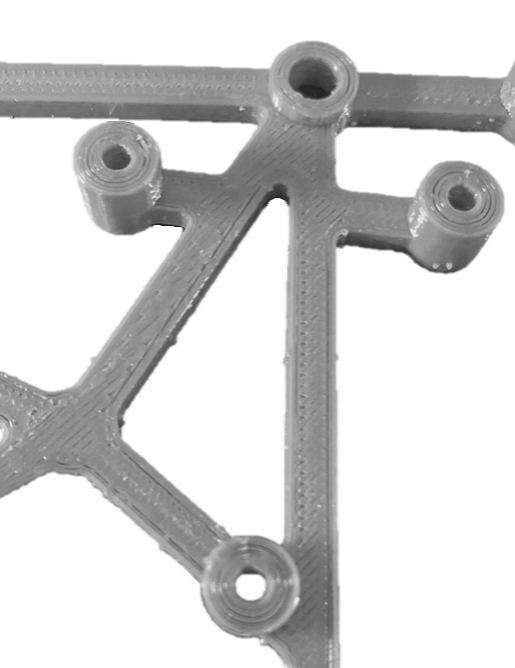
Based on the following generic model to evaluate the limits of an overhanging wall, we tested different configurations in order to see their impact on the result.
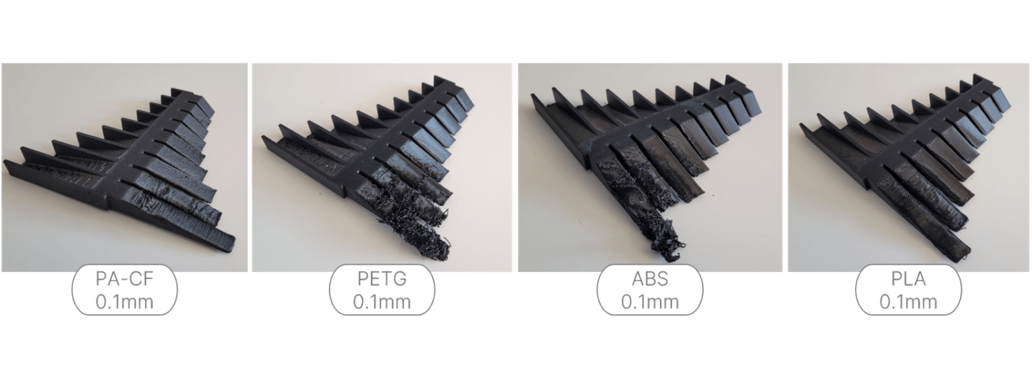
In the first test, we therefore varied the material while keeping the other factors:
In the second, we varied the thickness of the layers while keeping the same material:
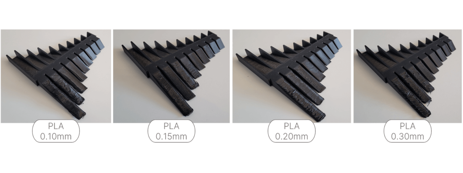
Observations following test print
The preceding images highlight the difference between a supported overhanging wall versus an unsupported wall. Another tangible observation is linked to the thickness of the layers: we notice that the thickness 0.15mm gives the best results for the wall overhanging 80°. With our printing settings, we can conclude that using a layer thickness of 0.15mm would be the most versatile option if one wishes to make a print without support material with PLA.
Troubleshooting Print Quality
Warping
Warping is one of the most common printing defects. Several solutions are possible to reduce the risk of warping:
- Keeping the room temperature constant reduces the unwanted and irregular contraction typically causing warping:
- Increase the temperature of the heating plate
- Print in a controlled environment
- Reduce or stop ventilation
- Create a more efficient contact surface with the plate:
- Apply adhesive to the tray:
- All Purpose Glue Sticks
- Magigoo
- Dimafix
- Use a Brim or a Raft
- Apply adhesive to the tray:
- Change the geometry of the part:
- Avoid straight corners
- Avoid residual stresses that could irregularly deform the part
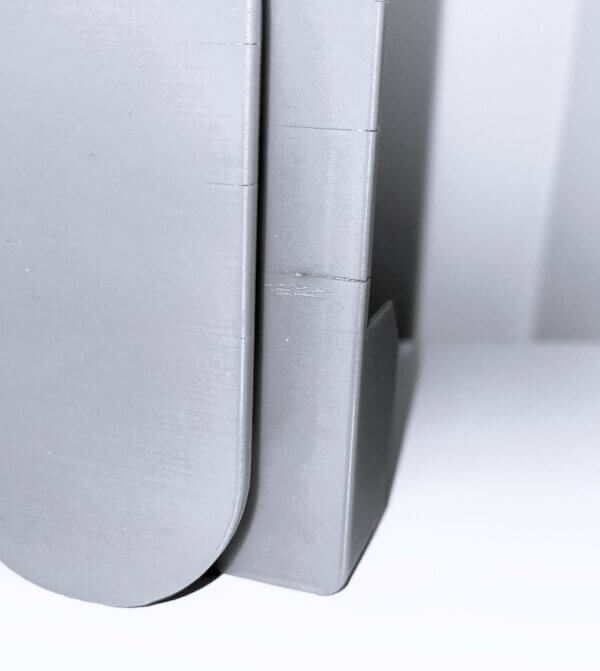
Splitting
FDM consists of depositing thin layers successively on top of each other. New material deposited on the previous layer must bond promptly to ensure the structural integrity of the part. A separation is due to a poor connection. In turn, poor binding can have several causes:
- Thickness of the layers: if the layer is greater than a value equivalent to 75% of the internal diameter of the nozzle, the pressure placed on the previous layer may be insufficient to attach to it.
- Nozzle Temperature: Hotter plastic is always more likely to stick to the previous surface than colder, harder plastic.
Inconsistent extrusion
An irregular extrusion is identified by an irregular shape of the visible walls. This aesthetic defect can also have significant impacts on the structure of the room. There are several possible reasons for this problem:
- Stuck filament: The first item to check is the filament spool. Indeed, a filament creating a varying voltage at the input will be reflected in an inconstancy at extrusion.
- Blocked nozzle: If the filament entry is not the cause, it is possible that the inconsistency is due to a small piece of plastic stuck in the nozzle. A visual inspection requiring removal of the nozzle is necessary to validate or refute this cause.
- Extruder slippage: Some materials have greater hardness than others. In this case, the extruder’s toothed wheel will be more likely to slide on the surface of the filament, changing the amount of material pushed into the nozzle. This can be adjusted by adjusting the force exerted by the gear on the filament.
- Print settings:
- The extrusion width is between 100% and 150% of the nozzle diameter
- The layer thickness is greater than 75% of the nozzle diameter
- Retraction speed or length must match system and material requirements
Layer shifting
This problem is mainly due to the fact that the majority of printers have open loop servos and do not know the position of the head in real time. The problem can have several causes:
- Mechanical problem: A physical restriction can interfere with the smooth movement of the head, such as a print head obstructed by a physical obstacle or a belt that is too tight;
- Acceleration of movements: The weight of the print head, as in the case of a direct drive, can cause a good inertia detrimental to the demanding accelerations configured in the slicer.
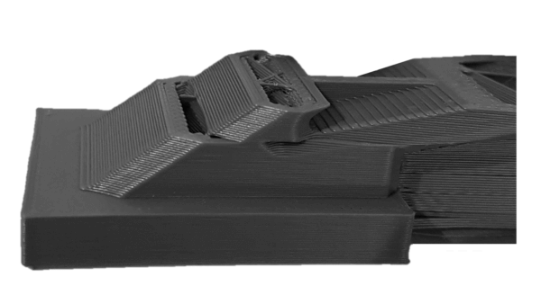
Small features hot printed
The target temperature for printing plastic depends on the material and environmental conditions. The balance is fragile between a material hot enough to adhere well to the previous layer and cold enough to solidify quickly providing the desired details:
- Insufficient ventilation: If the plastic does not cool quickly enough, it will warp under its own weight, erasing the small details of the part.
- Nozzle too hot: If the ventilation is active 100% of the time and the phenomenon is still present, it is possible that the material is simply too hot when extruded.
- Print speed too fast: If the previous layer is still cooling like in the case of a printed dowel, it is possible that the material is still too flexible and the weight of the new layer added is creating too much pressure and the part sags locally. To minimize this kind of problem, it is good to print other parts at the same time. This strategy allows time for the previous layer to cool before deposition of the molten wire from the upper layer.
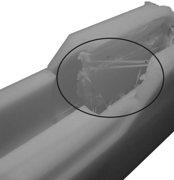
Stringing/Oozing
Hairs, stringing or oozing are seen much more with some materials than others. Indeed, this phenomenon is common when printing TPU. Oozing is created when the extrusion head moves from place to place between extrusions. Several printing parameters adjustments are possible to resolve this type of aesthetic defect:
- Retraction length: this parameter determines a length that will be transmitted to the extrusion stepper motor. This distance actually creates a considerable drop in pressure at the nozzle stopping the extrusion of the plastic. Insufficient length maintains pressure in the nozzle which contributes to unwanted loss; too long a length will result in plastic-free areas. Typically, a direct drive is a system that requires a much smaller length (approximately between 0.5mm and 2mm) of retraction than an extrusion system passing through a flexible tube (length of up to 15mm)
- Moisture in the material: Hygroscopic material (which absorbs moisture in the air) should be maintained in a drier. If the material was in non-ideal storage conditions and whiskers are seen on the part, it would be wise to dry the filament before attempting further parameter changes.
- Moving the print head: the longer the time between two extrusion moments, the greater the risk that a filament will escape from the nozzle and leave hairs on the part. To minimize time, slicers already take into consideration minimizing travel but it is also possible to try to increase the speed of movement of the head (called travel speed).
- Nozzle Temperature: A nozzle that is too hot will cause uncontrolled melting of the material and loss will be observed even if the filament pressure in the nozzle is reduced.
Elephant foot
Elephant foot is a phenomenon often noticed and little discussed since it is common and sometimes even seems intrinsic to the process. It is however possible to minimize this problem which presents itself as a sagging of the first layer(s) of the part. This issue decreases dimensional accuracy which can have a negative impact in an assembly situation requiring a more precise fit. Some ideas are presented to reduce this defect:
- Plastic Temperature: The main cause of this problem is that the heat bed keeps the plastic too hot and when the top layer is deposited, the bottom layer sags and creates this flared shape. To quickly reduce the temperature, you can reduce the temperature of the tray (it is recommended to try to reduce by 5°C per iteration) or increase ventilation during the first layers.
- Raft: a workaround strategy is to use Raft or Brim: without changing temperatures, Raft adds additional structure that helps limit crushing of the first layers.
- Chamfer: A final strategy is to add a chamfer to the 3D model. This chamfer will probably not be exact in its shape but it ensures that the deformation of the first layers will not influence the precision of the exterior walls.
Gaps
One of the most common pitfalls intrinsic to material extrusion is the lack of material deposited on the part which appears as a void on a visible surface. This problem is usually corrected by adjusting key parameters in the slicer:
- In the case that the gap is formed between the exterior wall and a top surface, the first parameter to consider would be linked to the overlap of the contour (Overlap). The default overlap percentage is 15%. Too much overlap can make the infill pattern visible on the external walls of the part.
- Another observable phenomenon linked to the lack of plastic in the part concerns the printing speed. Moving too quickly can harm the deposit of plastic. There is a balance between print head speed and extrusion speed.
- A general problem with plastic shortages is under-extrusion. This under-extrusion (or sometimes, over-extrusion) is influenced by the flow rate or over-extrusion ratio (“Flow Equalization Ratio”). This ratio controls the volume of plastic extruded . We typically aim for a ratio of 110% to fill the gaps, but certain configurations sometimes require varying this parameter.
- Depending on the shape of the gaps in the part, it is possible that the source of the defect comes from the filling ratio. Too little infill will have a negative impact on the sagging top surfaces due to lack of support. In such a case, it is also possible to increase the number of top layers to hide the defect.
- If gaps form on top of a thin wall, you can quickly correct the problem by activating a thin wall feature. It would also be possible to change the width of the extrusion trace to attach to the part.
Those challenges are more common with hobbyist range machines. Some Prosumer printers even prevent access to several of the parameters presented in this guide to simplify the process, such as the Eiger slicer used for Markforged printers. However, most slicers offer the freedom (and burden) of adjusting settings like IdeaMaker compatible with Raise3D, Cura with UltiMaker and Bambu Studio with Bambu Lab. The fact remains that these printers have increasingly accurate general parameters and tend towards closed architectures offering less latitude but with suitable results more easily achievable.
But still you have to choose the right process
The fact remains that FDM (or FFF) is only the tip of the 3D printing iceberg. Other methods are available and they have their own advantages, disadvantages and limitations. It is important when you want to print one or more parts to ensure that the right process is selected according to the context. Among the plastic additive manufacturing processes, in addition to material extrusion (FDM, FFF), there are the following technologies:
- Photopolymerization (SLA, DLP CLIP)
- Powder bed fusion (SLS, MJF)
- Material Jetting (MJ, PolyJet)
The Blog post 3D Printing – Variety of processes briefly presents these technologies and the resulting processes.
Disclaimers
The comments in this article are given to the best of Innovation M2’s knowledge. Please consult our disclaimers to understand the scope of the words in this article.
FDM is not always the solution
-
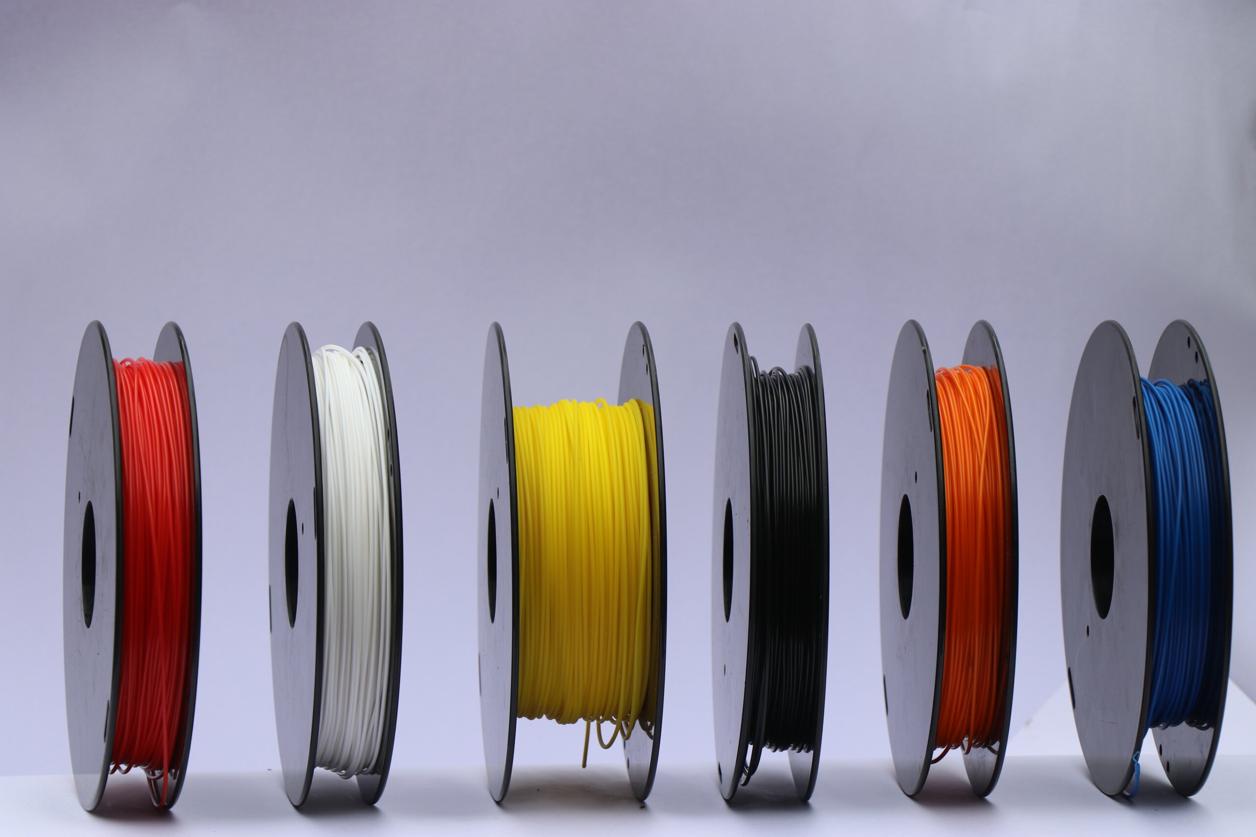
3D Printing - FDM - Filament Choice
Since the launch of the first 3D printer by Stratasys, only offering, at the time, ABS as a printing material, the plastic filament market has grown to now offer dozens of different materials. This expanded offering gives many opportunities and each filament can have its advantages and downsides depending on the purpose of the produced part. This article presents some filaments and their characteristics.
2023Expertise -
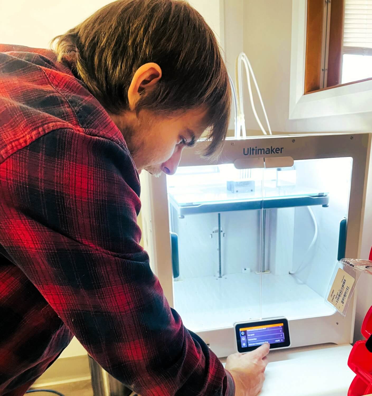
3D Printing - FDM - Desktop Printer
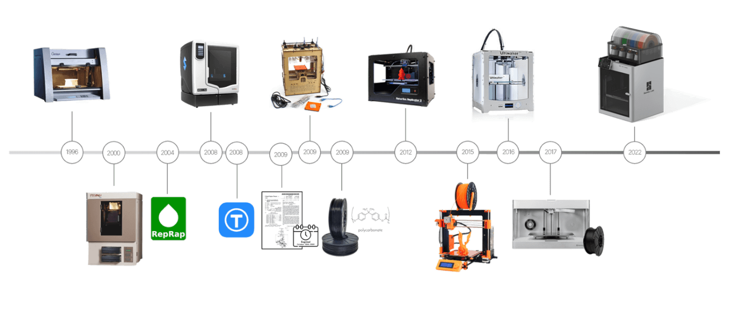
Fused deposition modeling, better known by the acronym FDM, is the most recognized additive manufacturing process. This "bit of history" blog post highlights the evolution of the desktop 3D printer in corporate engineering offices. We therefore focus on machines with a smaller form factor and on innovations making it possible to reduce acquisition cost.
2023Expertise