
3D Printing - Variety of processes
Expertise
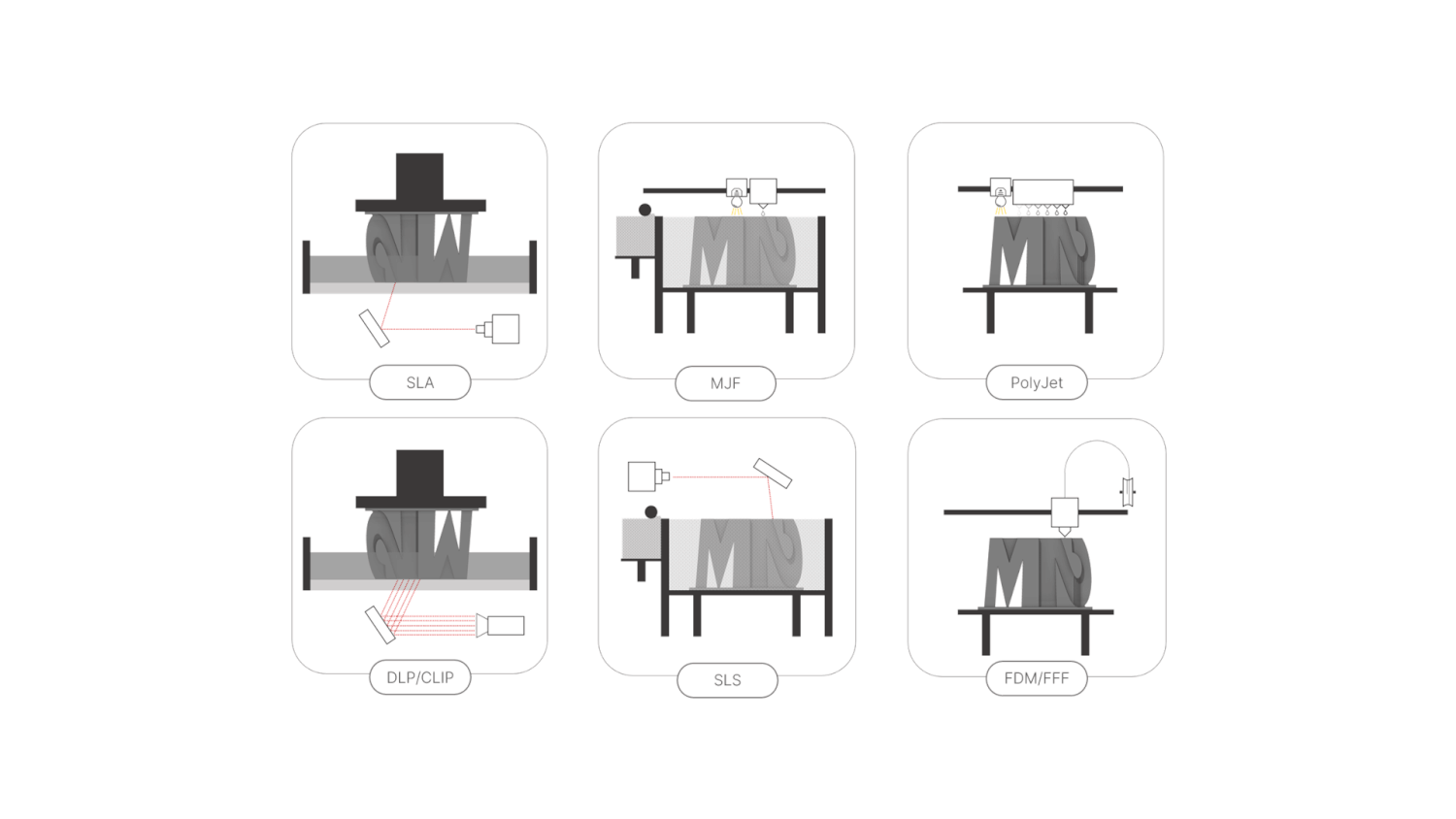
Additive manufacturing processes for plastic parts
There are a good number of 3D printing technologies available on the market. Understanding their working principles and discerning their differences allows you to choose the right process according to the needs of the application. This article highlights these differences by presenting them briefly and exposing certain limitations.
Stereolithography - SLA
A Slice of History – SLA
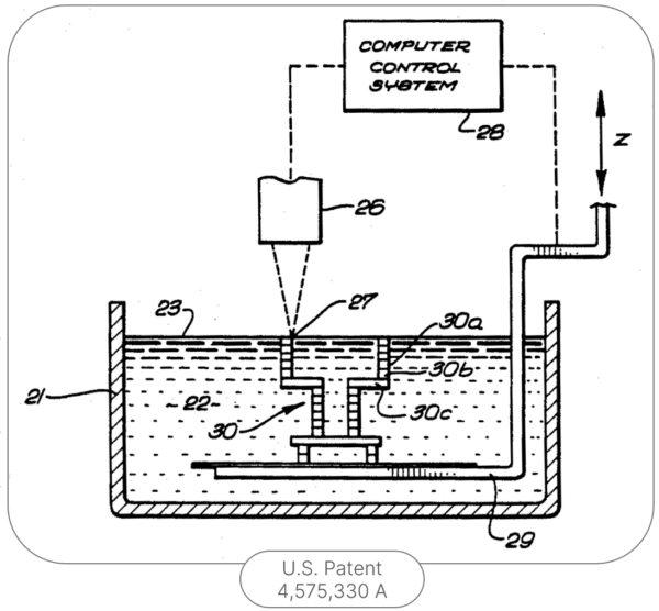
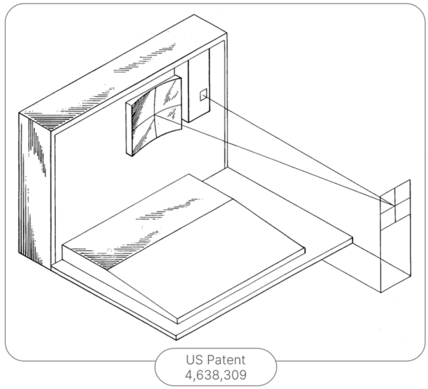
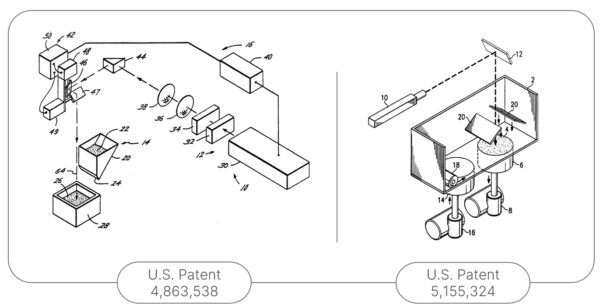
The history of stereolithography coincides with the genesis of 3D printing. In 1986, Charles W. Hull, co-founder of 3D Systems, filed the famous patent “Apparatus for Production of Three-Dimensional Objects by Stereolithography”. During his career, through around sixty patents, Hull will cover many aspects of additive manufacturing such as the STL file format, slicing of the 3D model, exposure time strategies to UV light and many others.
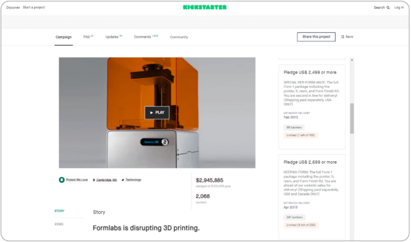
3D Systems is still an important day in the world of 3D printing today. Just as the Cupcake CNC came to change the course of things for FDM (for more information on the history of FDM, click here), in the same way, through a Kickstarter campaign, Formlabs introduced to the market a 3D printer based on SLA technology for the hobbyist market in 2012. Since then, several SLA and DLP 3D printers have appeared and have democratized accessibility to this technology.
Working principle – SLA
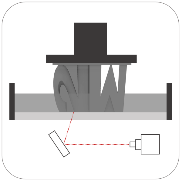
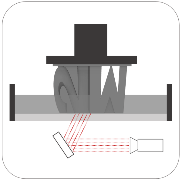
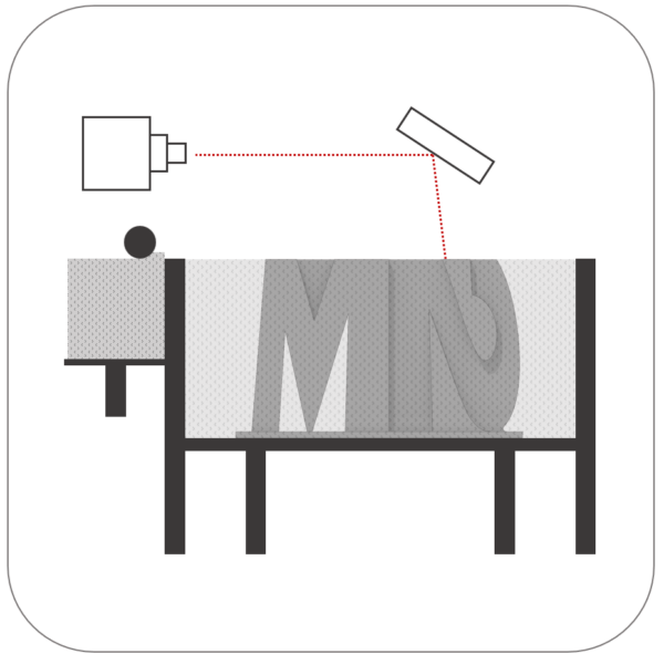
Stereolithography (SLA) is a resin vat polymerization additive manufacturing process: a liquid photosensitive resin is poured into a tank and UV light interacts with the resin to polymerize it.
The UV light beam is aimed by a motorized mirror and this UV light cures the resin layer by layer pulling the part out of the tank the same distance until the final object is complete. The layer thickness is established according to the desired resolution:
- Standard resolution: 0.100mm
- High resolution: 0.050mm
- Micro resolution: 0.025mm
Once the print is finished, you end up with a part stuck on the print bed. The part is typically in a mixed orientation which is determined based on favorable resin flow. Indeed, by withdrawing, layer by layer from the tank, the resin must flow well to return to the tank. The areas retaining the resin will affect the surface definition on these trapping areas.
After being removed from the board, the part is washed in a bath of isopropyl alcohol. It is then hardened (cured) in a UV chamber and heated. The curing time in the chamber as well as the temperature to which the chamber is heated will have an impact on the structural characteristics of the room.
Finally, the supports are removed. (Some methods indicate to start with the media removal step before the bath and UV chamber)
There is subsequently a range of treatments that the part can undergo, such as polishing in the case of a translucent part that we would like to make transparent.
Due to the fact that the resin is photosensitive, its exposure to external conditions produces premature aging of the part. This fact remains the greatest limitation of the process.
Materials – SLA
The materials that are available for this manufacturing process are necessarily photoreactive thermosetting materials. These materials are called resins and exposure to UV rays activates their agglomeration. The range of resins available on the market is impressive. Here are some categories encompassing groups of resins:
- Standard resin: The main advantage of standard resins is that they are very affordable. (Ex.: Accura AMX Rigid Black)
- High resolution resin: High-resolution resins deliver high-resolution, rigid prints with a smooth surface finish. (Ex.: ProtoLab MicroFine)
- Transparent resin: Transparent resins, having mechanical properties similar to standard resins, have the ability to be almost transparent after post-processing. (Ex.: Accura ClearVue)
- Tough resin: Tough resins have mechanical properties similar to ABS. (Ex.: Accura Xtreme White 200)
- Semi-flexible resin: Semi-flexible resins have mechanical properties similar to PP. (Ex.: Somos 9120)
- Heat resistant resin: Heat resistant resins offer heat deflection temperatures between 200 and 300°C. (Ex.: Accura Bluestone)
- Fire resistant resin: Fire resistant resins typically meet the UL 94 V-0 requirement for a 3mm wall. (Ex.: FormLabs Flame Retardant)
- Fexible resin: Flexible resins allow parts to be prototyped later made from rubber or polyurethane. (Ex.: FormLabs Elastic 50A)
- Ceramic-like resin: These resins reinforced with ceramic particles provide high rigidity, resist high temperatures and produce smooth surfaces in prints. (Ex.: Adv. HighTemp PerFORM)
- Class I biocompatible resin: Class I biocompatible resins are commonly used in medical applications requiring autoclave sterilization. (Ex.: FormLabs BioMed White)
- Class IIa biocompatible resin: Class IIa biocompatible resins are specifically designed for long-term dental and orthodontic applications. (Ex.: FormLabs BioMed Clear)
- Silicone: Silicone is available in a range of durometers varying between 20A and 60A. Silicone also meets class I biocompatibility. (Ex.: True Silicone)
Design Guidelines – SLA
When designing a part for SLA or when modifying a concept to prototype in SLA, we must keep in mind the operating principle, recognize the advantages and disadvantages of this technology and ensure that the part is designed accordingly . For example, the excess thicknesses will be full which can be expensive. To minimize resin consumption, it is possible to design parts with hollow cavities. To allow uncured resin to escape, it is advisable to size the drip holes to be greater than 4mm in diameter.
Layer thickness
As mentioned previously, thicknesses are generally defined by the resolution:
- Standard resolution : 0.100mm
- High resolution : 0.050mm
- Micro resolution : 0.025mm *(limits the choice of materials)
Minimum features size
Unsupported walls are more likely to detach from the rest of the part during printing or break quickly once the part has cured. The process, however, gives the opportunity to obtain fine detail. The minimum size of a supported wall for a micro resolution part is between 0.06mm and 0.2mm. For high and standard resolutions, the minimum detail size is between 0.1mm and 0.4mm. The smallest part that micro resolution can be produced is a part measuring 0.63mm x 0.63mm x 0.63mm.
Hole
For the hole to be well defined, its diameter must have a dimension that allows the resin to escape. The minimum hole size depends, once again, on the resolution:
- Standard resolution : Ø0.6mm
- High resolution : Ø0.5mm
- Micro resolution : Ø0.4mm
Overhanging wall
The maximum angle of the overhanging wall without support is 19° for a distance of 1.0mm.
Dimensional Accuracy
Dimensional tolerances depend on the printing plan and the printer itself but, generally speaking, we can consider as follow:
- XY plane: ±0.05mm + ±0.001mm per mm
- Z axis : ± 0.13mm + ± 0.001mm per mm
Digital Light Processing - DLP
A Slice of History – DLP
We could have put SLA and DLP in the same block, but the differences between the two processes are such that it is good to distinguish them in order to choose the right process in given conditions.
Digital light processing, or DLP, is actually an image projection technology. A DLP chip is composed of an array of micro-mirrors shown on pivots. Each mirror corresponds to one pixel.
The first company to produce a printer using DLP instead of laser was EnvisionTEC in 2002. Subsequently, dozens of companies integrated this technology since the cost of the system is lower than the cost of a laser system associated with SLA technology.
Since the integration of DLP, the technology has evolved with a number of acronyms: CDLP, mSLA, DLS, CLIP, P3, DPP, LSPc, MOVINGLight. The process remains very similar to DLP by including the principle of a continuously moving Z axis.
Among the companies active in the development of these technologies are Carbon3D, Nexa3D, ETEC (formerly EnvisionTEC) and Stratasys Origin.
Working principle – DLP
DLP is a resin vat polymerization additive manufacturing process: a liquid photosensitive resin is poured into a tank and UV light interacts with the resin to polymerize it. The process is very similar to SLA but the pixel cures over a defined thickness. This theoretical cube is called a voxel. Classic DLP can give a staircase finish where we see the impact of these voxels. In return, the continuous version, CDLP creates a smoothed surface and beautiful definition.
Considering that the process impacts a minimum of heat, this process has no, or very little, risk of warping.
The pros and cons are very similar to SLA.
Materials – DLP
The materials available are similar to SLA. Although some SLA materials are compatible with DLP printers, it should not be assumed that all of them are. There are some interesting materials targeting DLP specifically (named by one of its many variations) as the process of choice in certain cases:
- Transparent resin PP-Like: Transparent prototyping sometimes allows more information to be given during tests than with an opaque material. PP is an interesting material to simulate a future product in a resilient material. (Nexa3D xPP405 Clear)
- Flexible biocompatible material: Patient contact materials used in a medical product must be biocompatible. Flexible biocompatible materials are less common than rigid ones. Although the material is biocompatible, it is likely that the part produced must also be tested for biocompatibility. (Carbon EPU 41)
- Ceramic-like resin: These resins reinforced with ceramic particles provide high rigidity, resist high temperatures and produce smooth surfaces in prints. (Ex.: Nexa3D xCERAMIC3280)
- Heat resistance resin: Heat resistant resins offer heat deflection temperatures between 200 and 300°C. Their characteristics can, in some cases, resemble engineering materials like PEEK. (Ex. : Nexa3D xPEEK147)
- Impact resistant resin: Enclosures containing electronics are typically subject to drop tests. Several moving parts of a mechanism are also prone to impacts. Some resins are designed specifically for this kind of mechanical stress. (Ex. : LOCTITE Dura56)
Design Guidelines – DLP
Designing a part by DLP is very similar to the design philosophy by SLA. The process is very permissive. Considering that the materials are photocurable, it is not recommended to use parts made from this process outdoors and exposed to sunlight.
Layer thickness
DLP resolution typically vary between 0.005mm and 0.15mm
Minimum features size
Unlike SLA, the size of the details varies depending on the size of the part in general. The size of the printing surface is proportional to the detail since the number of pixels of the project is defined. In addition, the detail on the periphery of the printing plate receives a smaller amount of energy than in its center.
Small details can be as small as 0.1mm and thin walls can be as small as 0.3mm.
For the holes, shallow cavities of approximately Ø0.25mm can be designed. A 3.5mm high stud could have a diameter of 0.4mm. Everything remains considerably risky during post-processing.
Dimensional Accuracy
For a resolution of 0.07mm, the expected dimensional tolerance is ±0.15mm;
±0.2mm for a resolution of 0.1mm.
Selective Laser Sintering - SLS
A Slice of History – SLS
Selective Laser Sintering (SLS) technology began in the late 1980s by Dr. Carl Deckard and Dr. Joseph Beaman of the University of Texas at Austin. Initial patents for SLS were granted to the university beginning in 1989, and the technology was licensed to DTM Corporation.
In 2001, 3D Systems acquired DTM making them the market leader in 3D printing by controlling SLA and SLS. Their SLS machines are widely used in a variety of industries, including aerospace, automotive and healthcare.
However, in recent years, bold small companies have entered the market offering more affordable and accessible SLS technology. One such company is Sinterit, a Polish startup founded in 2014. Sinterit has developed a line of SLS machines that are smaller and more affordable than traditional SLS machines, making the technology accessible to small and medium-sized businesses.
Another company that has disrupted the SLS market is Formlabs. Following in the footsteps of 3D Systems, Formlabs, which was mentioned above in the SLA, in 2017 launched the Fuse 1, a compact and affordable (around $10k USD) SLS machine designed for the Prosumer market.
Working principle – SLS
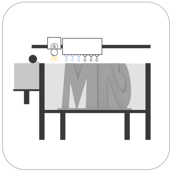
The principle of selective laser sintering (SLS) is to use a high-power laser to fuse small particles of powdered plastic layer by layer, until a three-dimensional object is formed. The chamber that contains the plastic powder is preheated close to the melting temperature of the plastic to facilitate the fusion made by the laser. The process involves first spreading a thin layer of powdered polymers onto a build platform using a roller or broom. Then, a laser scans the surface of the powder, causing the particles to sinter (melt) in the areas where the object is to be formed, according to a 3D model. Once the entire layer has been solidified by the laser trajectory, the platform lowers and a new layer of powder is spread on top, then the process is repeated until the final object is completed.
Once printing is complete, the part is hidden in the compacted plastic powder block. To free the part, a dusting step is required. At this point, the part is usable, however, its surface is rough and, for dark powder parts, the color remains quite pale. There are therefore several finishing stages to obtain a finished and elegant product.
Finishing Steps
- Sanding, Sandblasting, Blasting: The surface of the part may need to be sanded to achieve a smoother finish.
- Surface treatment: Depending on the application, it may be necessary to treat the surface of the part to improve its properties, for example by applying a coating or passing through a dye tank.
- Heat treatment: To achieve the desired mechanical properties (e.g.: strength, durability, rigidity), certain materials need a second annealing step.Installation of inserts: Generally speaking, a plastic that undergoes multiple screwing/unscrewing should have inserts to prevent premature wear of the threads. This fact is all the more true for printing products. Although the material offers interesting properties, it remains less efficient than extruded or molded plastic.
- Machining: Using machining as a secondary operation for a printed part is quite rare but this option remains available in the case that the shape is better suited to printing but the need for precision exceeds that offered by the technology. This approach has already been used by members of the M2 Innovation team in such a context.
Advantages
- Complex geometries: The main advantage of SLS over other 3D printing technologies is that it can create parts with complex geometries and functional properties, without the need for support structures. This is because the powder material provides its own support during the construction of the part. Additionally, SLS can use a wide range of materials, including those with high melting points or those that are difficult to mold using traditional manufacturing techniques.
- Mechanical properties: Structurally, the finished part offers interesting mechanical properties which makes the technology viable for production.
- Low entry cost: The fact that no tooling costs are required makes the process useful and relevant for prototyping and possibly the first production units of a product.
Process limitations
- Dimensional Tolerances: Although the process offers great versatility in possible geometries, it is difficult to combine the precision of tolerances with a smooth surface finish and surface treatment such as the application of a coating. Indeed, the finishing steps are generally manual tasks, which means that manual sanding results in variability in the dimensional tolerance of the part. The same is true with the application of paint or other coating.
- Warping: Another well-known limitation of SLS is the risk of warping: the basics of this process involves the fusion of successive layers of plastic. This heat distributed irregularly in the room induces residual stresses which can cause deformation. It is therefore not recommended to attempt to print straight, thin parts with low inertia.
- Inaccuracy in detail: The diameter of the laser beam is approximately 0.3mm. This physical property limits the detail that SLS can give.
- Unit cost: Considering the necessary post-processing steps and the significant cost of industrial machines, the cost per part of such a process remains high and therefore becomes more expensive than injection quite quickly in production.
Materials – SLS
To be compatible with SLS technology, the polymer must have the ability to soften when heated sufficiently, but, upon cooling, becomes hard again while retaining these initial properties. Materials that have this ability are called thermoplastics. The opposite of a thermoplastic is thermoset (used in SLA). Although initially only nylon was available in SLS, there are now several different accessible materials:
- Nylon: Resistant to abrasion and impacts, nylon is the generic material used in SLS. (Ex.: Sinterit PA11 Onyx)
- Reinforced nylon: Reinforced nylon contains an additive that greatly changes its properties. It can be doped with fiberglass or carbon, increasing its rigidity and its resistance to heat. The additive can also make the nylon ESD (Electrostatic Discharge) or FR (Flame Retardant).(Ex.: Ultrasint PA11 Black CF)
- PBT: PBT has good resistance to chemicals and offers good electrical insulation. It is frequently used in connectors (Ex.: Addigy P1210)
- PEKK: PEKK is very resistant to heat in addition to having great rigidity (Ex.: HexPEKK-100)
- PEEK: PEEK is a high-end engineering material widely used in cases of wear resistance or in cases of frequent autoclave sterilization. (Ex.: EOS PEEK HP3)
- Polyurethane: Useful for testing flexible parts like a pipe or bumper. Several options can be found on the market offering duros between 59A and 95A (Ex.: DuraForm TPU 59A)
- Poypropylene: PP typically has a duro 50D which is equivalent to a 95A offering great flexibility. PP has very good chemical resistance and its density indicates its buoyancy. (Ex.: Sinterit PP)
- Biocompatible elastomer: These elastomers are heat and autoclave resistant. This choice is therefore the best option for the need for a flexible sterilizable material. (Ex.: Addigy P3001)
Design Guidelines – SLS
The design of SLS parts must take into account the advantages and disadvantages of the process. When an SLS part is printed, it “floats” in a bath of plastic particles. It is often said that the process does not require supports. Although it is true, the same way we need to remove supports from a FDM part, the product of an SLS print needs to be freed from the powder that has been compacted by a roller between each layer. In addition, the powder surrounding the outer surface is also affected by the fusion of neighboring particles.
Dimensions
The maximum size that can be manufactured depends on the machine used. For example, Stratasys Direct can manufacture PA12 parts with a maximum dimension of 673mm x 343mm x 508mm. Protolabs offers a more cubic maximum format of 482mm x 482mm x 431mm.
The Formlabs Fuse 1 allows you to print a part measuring 159mm x 159mm x 295mm.
However, you must keep in mind that the larger the part, the more likely it is to warp. The rule of thumb of the process is that the part should not exceed 330mm in any direction.
Layer thickness
Typically, the resolution offered on the Z axis is 0.1mm (0.004″). However, some printers offer better resolution by reducing the minimum layer height to 0.06mm.
Features size
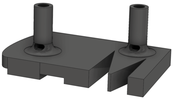
Small walls less than 1mm high oriented in the Z direction can have a thickness of 0.6mm and 0.3mm when oriented on the XY plane. Walls more than 1mm high should have a thickness of at least 0.7mm. According to a rule of thumb, a good-sized room should have walls of at least 1mm. Walls greater than 5mm should be hollowed out. The recess holes must be at least Ø3.5mm. A good design requires 2 holes (one to push the powder and the other to let it escape; see an example of holes later in the text). Small details like studs must have at least Ø0.8mm and a radius in the joint to reinforce the bond. The risk is mainly to break the stud during dusting.
Hole
For the hole to be well defined, its diameter must have a dimension that allows the plastic particles to escape. The rules of thumb often define this hole with a dimension of Ø1.0mm. A well-designed hole would meet at least one of the following two criteria:
- The hole size is a standard drill bit size to re-drill the hole in post-processing.
- The hole opens out the other side to allow the powder to escape more easily when pushed.
To help understand point 2, here is a small illustration of how to go about it:
The space between walls follows the same logic: a space that is too small is difficult to clean. Furthermore, the SLS is the product of a heat exchange which causes the part to shrink when cooling. To compensate for this contraction, we suggest oversizing the openings requiring a certain desired precision of a value between 0.15mm and 0.20mm.
Dimensional Accuracy
Dimensional tolerances are in general estimated at ±0.05mm/mm with a minimum of ±0.3mm.
Multi Jet Fusion - MJF
A Slice of History – MJF
Around 2010, SLS was a widespread prototyping process; we already knew its advantages and limitations. Although using it in production was a fringe solution, the process remained a common solution for functional prototypes by offering an interesting range of materials. In 2016, HP unveiled a new printing technology similar to both SLS and Binder jetting. Multi Jet Fusion quickly becomes interesting: although initially, the only material available was black Nylon PA 12, its mechanical properties were similar to SLS but with finer definition of details and smoother walls. Its lower cost than SLS also added weight to the interest linked to MJF technology.
Working principle – MJF
Like SLS, Multi Jet Fusion is based on the principle of a powder bed (typically, a polyamide powder). A thin layer of particles is deposited on the bed. Layer thickness equals print resolution. The bed is in a chamber heated to a temperature slightly below the melting point of plastic. On the layer is deposited a special ink composed of a fusion agent which reacts to infrared radiation (causing the fusion of particles) and a dispersion agent which helps to control the propagation of heat (avoiding air bubbles in periphery of the room). The ink droplets have a size of approximately Ø0.02mm which offers the possibility of better detailing of parts than with the Ø0.3mm laser beam for SLS.
Once the ink layer is applied to the powder layer, a source of infrared radiation interacts with the surface melting the powder where the fusing agent is deposited and evaporating the dispersing agent applied around the fusing agent . The same process is repeated layer after layer until the final part is obtained.
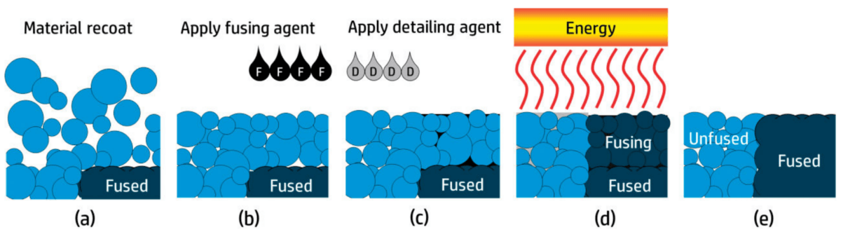
Image taken from HP User Guide
In the same way as with SLS, the part is released from the powder bed and cleaned to obtain the finished product. It is estimated that around 80% of the powder recovered in the post-processing station is recyclable for a new print (for SLS, this ratio is estimated at 50%). Once the majority of the powder has been removed, several media are used to finalize the cleaning of the part:
- Air blasting
- Waterjet blasting
- Beadblasting
- Sandblasting
Advantages
- Complex geometries: MJF offers similar opportunities to SLS in terms of available geometries in addition to offering better details of small details.
- Mechanical properties: Structurally, the finished part offers interesting mechanical properties which makes the technology viable for production.
- Constant color: The fusion agent deposited on all layers colors the part both outside and inside, which is advantageous compared to a dye which penetrates approximately 0.5mm for a white part printed in SLS .
- Relatively low cost: Compared to other printing processes, MJF is one of the cheapest processes due to its high ratio of recyclable material and its printing speed.
Process limitations
- Thick wall: Although the limit in terms of geometry is quite low, thick walls are the Achilles heel of the process. A high concentration of material gives rise to uneven curing and cooling which results in a visible surface defect called “Elephant skin”.
- Limited choice of materials: Initially, only black PA 12 was available. Since then, several materials (presented below) have become available, but the choice remains very limited compared to other processes.
- Warping: Another well-known limitation of MJF is the risk of warping: the basics of this process involves the fusion of successive layers of plastic. This heat distributed irregularly in the room induces residual stresses which can cause deformation. It is therefore not recommended to attempt to print straight, thin parts with low inertia.
Materials – MJF
As with SLS, the process is only compatible with thermoplastics. The choice of materials remains limited although it grows every year:
- Nylon: Original material of the process which has evolved a lot since: we can now have white nylon with colored ink to have access to several colors (only black was originally available) (Ex.: HP 3D High Reusability PA 12 W)
- Reinforced nylon: Nylon reinforced with glass beads useful for the manufacture of tools requiring rigidity (Ex.: HP 3D High Reusability PA 12 Glass Beads)
- Flexible nylon: Called TPA, this material offers properties similar to traditional nylon by offering improved flexibility. (Ex.: HP 3D High Reusability TPA)
- Polypropylene: PP is a biocompatible material (contact with skin) and can be used in cases of plastic welding with another polypropylene part (Ex.: HP 3D High Reusability PP)
- Thermo Polyurethane: With such high impact resistance, this material is an excellent choice for a piece used as a bumper or ergonomic support (Ex.: ESTANE 3D TPU M88A-565)
Design Guidelines – MJF
The design of a part in MJF is quite similar to what must be done in SLS except that the design is more affected by excess thickness. However, it offers more refinement on small details.
Dimensions
The maximum part size is defined by the size of the print bed, i.e. 380mm x 285mm x 380mm. However, considering that the process is prone to warping, it is not recommended to print long thin parts or parts with abrupt thickness variation. The length to width ratio should be less than 10:1 at all times. Thickness variations should include good sized radii.
Considering that the process is sensitive to very thick walls, it is recommended to create hollow parts in order to obtain fairly constant walls.
Layer thickness
The thickness of the layers is typically 0.08mm.
Features size
The MJF is able to print walls as thin as 0.5mm. These must, however, be short enough and ideally supported to withstand post-processing.
A stud or cylindrical shape can be as thin as 0.5mm in diameter. The smallest details can reach 0.1mm.
The minimum gap space is also 0.5mm.
The diameter of a hole must also be greater than 0.5mm.
Dimensional Accuracy
Dimensional tolerances are estimated at ±0.2mm for dimensions less than 100mm and ±0.2% for dimensions greater than 100mm.
Material Jetting - PolyJet
A Slice of History – PolyJet
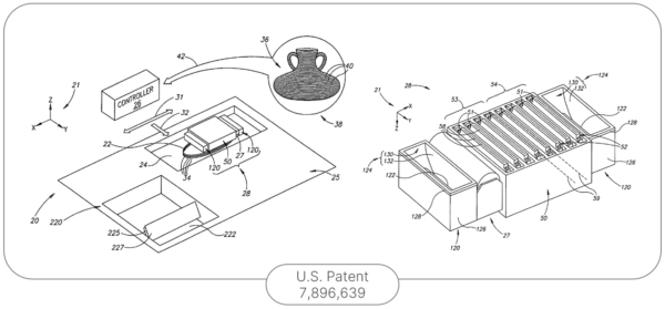
Originally developed by Israeli company Objet Geometries in the early 2000s, PolyJet printing technology is inspired by advances in thermosetting materials made by SLA since the 1980s and inkjet printing technology capable of producing a beautiful definition of images.
The first machine put on the market by Objet, the Eden260V, already had a fine resolution of 16 microns.
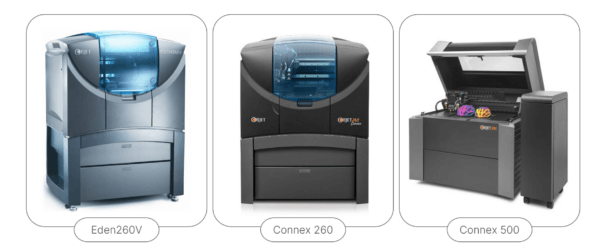
- In 2007, Objet introduced Connex which allows several materials to be combined in a single piece. This characteristic corresponds to what we mean today by PolyJet.
- In 2012, Objet joined Stratasys, which continued the development of this technology by creating the J750. This new printer model uses a special print head with six channels, each containing a different color. Colors are mixed in the room to create one of 500,000 available shade combinations as well as realistic textures. In parallel, another printer, the Connex3, allows the printing of rigid and flexible materials in a single part.
Working principle – PolyJet
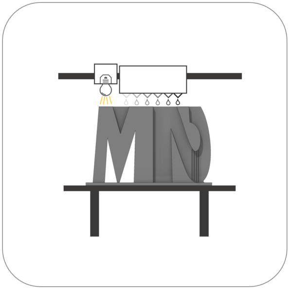
PolyJet is a liquid material deposition 3D printing technology. It uses a process similar to inkjet printing as mentioned previously. A liquid is sprayed through a print head and deposited onto a print bed in successive layers. The main difference is that, instead of using ink, PolyJet uses thermosetting materials.
When printing, the print head moves back and forth across the print bed, spraying liquid materials through very fine nozzles. The materials are sprayed in successive layers, and each layer is cured by a UV light source. The build bed then moves down one level (equivalent to resolution), and the spraying and curing process continues until the part is fully built.
Advantages
- High level of detail: One of the important characteristics of the PolyJet is its ability to produce parts with very fine details and smooth surfaces. This precision is due to the print head’s fine nozzles, which can produce layers just a few microns thick.
- Overmolding Prototyping: PolyJet can print a wide variety of materials, from rigid plastics to flexible elastomers to transparent materials and composite materials.
- Color: New PolyJet printers like the J750 can print in color, which is particularly useful for prototyping finished parts and for design applications. PolyJet printers are capable of reproducing a wide color gamut with great precision.
- Soluble Supports: The PolyJet uses soluble supports that dissolve in water, which facilitates the post-processing process and allows the production of complex parts with internal geometries.
Process limitations
- Cost: The cost of running a Polyjet printer is generally higher than FDM or SLA 3D printers. The consumables are also relatively expensive, which makes the final part expensive.
- Durability: Although parts printed in Polyjet are generally very precise, they may not be as durable as parts produced by other 3D printing processes such as thermoplastics. In fact, thermohardeners exposed to UV rays continue to degrade and age prematurely.
- Limited materials: Several colors and textures can be applied to the printed parts; however, materials are limited compared to other 3D printing processes.
Materials – PolyJet
PolyJet has dozens of materials offering different mechanical properties, colors, textures and durancies. It is even possible to combine them to obtain different properties. Here are some interesting materials:
- Transparent flexible dental resin: A unique material offered only in PolyJet is Flexible Clear Biocompatible MED625FLX. It combines many of the advantages of PolyJet printing (Biocompatibility, Duro A77, Transparency)
- Colored photopolymer: The Vero brand offers numerous colored resins which can be combined to obtain vibrant models. The Vero is also available in a transparent materials.
- Flexible materials: The most common flexible PolyJet material is Agilus (30A to 90A). Agilus is also available in different colors..
- Ultimately, the process delivers resins that simulate common materials like ABS and Polypropylene. These so-called digital materials are in reality the combination of several resins simulating the desired properties.
Design Guidelines – PolyJet
In order to properly design or modify a part that will be produced in PolyJet, it is essential to keep in mind how the process works. The variety of the finished product is very vast: you can obtain a glossy or matte finish, a piece of several colors or transparent or a combination of colors and transparency, different hardnesses, different properties on the piece and varied textures. The product remains made of thermohardeners which means that it still degrades quite quickly in outdoor conditions.
Dimensions
The maximum part size depends on the printer used. Typically, we can design a part that can be placed in an envelope of 490mm x 390mm x 200mm. A smaller printer like the Objet30 has a working volume of 294mm x 192mm x 148mm.
Layers thickness
Layer thickness varies depending on resolution and is usually between 0.016mm and 0.036mm.
Features size
The minimum detail size depends on several factors including the resolution of the print and the resins used. However, the minimum thickness of walls and details in the room is generally 1.2mm for rigid materials and 2mm for elastic materials. The same goes for studs: for a rigid part, it is possible to produce a small cylinder of 0.5mm (0.8mm for elastic materials). The fact remains that it is a fragile detail and at risk of breaking during post-processing. A Ø1mm rod is likely to survive the entire manufacturing process better.
Hole
It is possible to produce parts with a hole as small as Ø0.5mm. In the same way as for several printing processes, it is strongly recommended to design the holes which correspond to standard drill bit dimensions to allow the hole to be re-drilled after printing and guarantee better precision.
Dimensional Accuracy
Dimensional tolerances are ±0.02mm per mm and, at least±0.1mm.
Conclusion
3D printing is still evolving. There are currently several other processes available on the market which mainly consist of the evolution of existing technology.
Metal additive manufacturing processes, such as DMLS for example, are not covered in this article. However, it is good to say that, contrary to what one might think, DMLS is more similar to SLA than to SLS in terms of the limits of the process. Indeed, since supports are necessary and must be removed in post-processing, a design similar to SLA is required.
FDM is covered in a separate article. To have the design guidelines for this process, it’s here.
Ultimately, this article presents a wide range of available technologies. However, it is important to design the parts or modify them according to the chosen process to produce (or receive) a relevant and expected result.
There are dozens of materials available and their selection complicates the prototyping process, but this choice is just as important as that of the process to have a result that meets expectations and will fulfill the desired function of the prototype or final product.
Disclaimers
The comments in this article are given to the best of Innovation M2’s knowledge. Please consult our disclaimers to understand the scope of the words in this article.
3D printing is regularly used in the products we design
-
3D Printing - FDM - Design Guidelines
At first glance, fused deposition modeling printing (FDM) seems quite simple. Indeed, almost all geometries can be manufactured by FDM. However, it is possible to optimize the design of a part in order to have a good finish, to avoid "post-processing" and to keep a desired geometry.
2023Expertise -
3D Printing - FDM - Desktop Printer
Fused deposition modeling, better known by the acronym FDM, is the most recognized additive manufacturing process. This "bit of history" blog post highlights the evolution of the desktop 3D printer in corporate engineering offices. We therefore focus on machines with a smaller form factor and on innovations making it possible to reduce acquisition cost.
2023Expertise